Overivew
- ASA supported routed and bridge mode
- Default mode is routed
- ASA can work like switch, however with firewall features.
- to Bridge two vlan, ASA must be part of same subnet
- Advantage transparent
- we can insert our firewall without make any changes IP address of devices.
- Disadvantage:
- support only VPN fir management, VPN site to site , remote access not support
- doesnt support QoS
- doesnt support NAT
- doesnt support Routing protcols and Ipv6
- In transparent from high security level to allow is permit except mulicast.
Topology
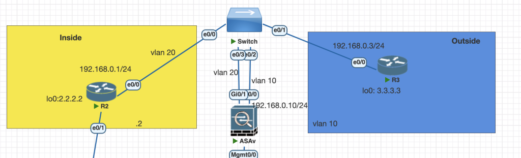
in this Topology R2 and R3 separated by Cisco ASA and attached with switch, the subnet address is in one networks.
The switch provide access vlan for each R3, R3 and Cisco ASA.
Testing Scenarios
- R2 and R3 have been pre-configured with IP addressing and OSPF. However, R2 and R3 are not able to establish OSPF adjacency. Configure ASAx1 to bridge Vlan 10 and Vlan 20 so that R1 and R2 can establish OSPF adjacency between each other.
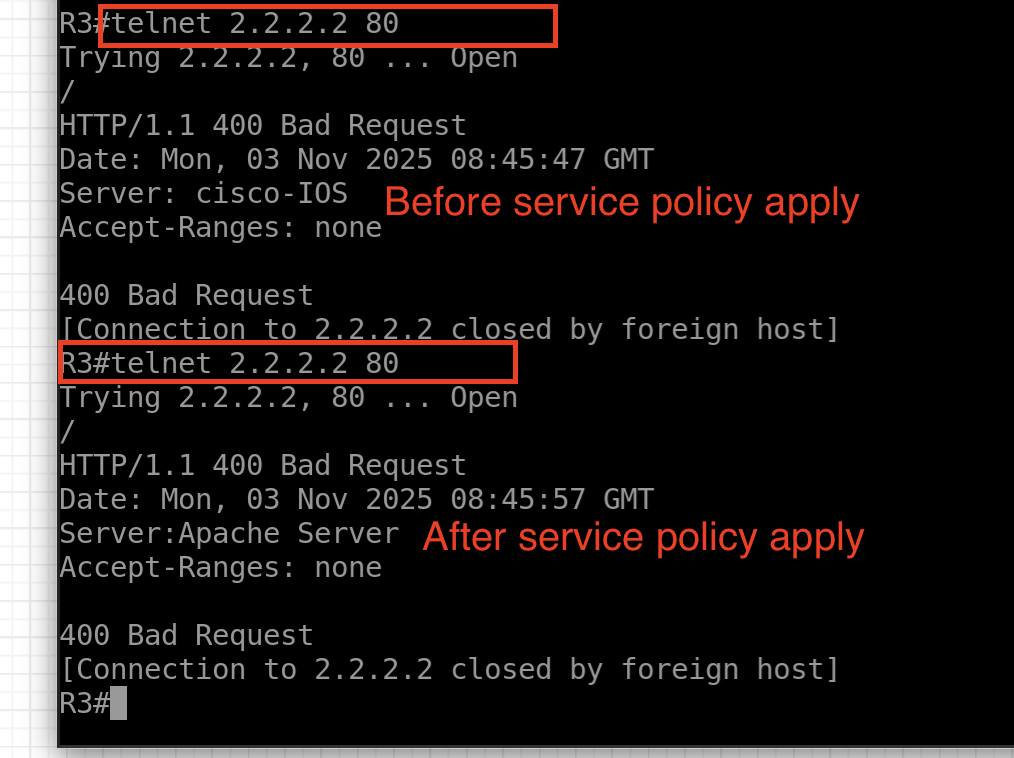
- R2 is simulated as a web-server. When anyone from the outside accesses this web-server, the ASAX1 must spoof the server header field to display the web-server as an “Apache Server” instead of a Cisco Router.
Configurations
Scenario 1
- Change transparent mode cisco ASA and configure bridge and interface IP BVI.
conf t
firewall transparent
int bvi 1
  ip address 192.168.0.10 255.255.255.0
int gi 0/1
  nameif INSIDE
  no shutdown
int gi 0/0
  nameif OUTSIDE
  no shutdown
2. In transparent mode all traffic from high security level to lower security is allowed except multicast. With this knowledge the adjacency OSPF will broken between R2 and R3. we need to define 2 access list to solve scenario 1
- Allow incoming ospf from outside to inside network
- Allow any traffic from inside into outside network
access-list OUTSIDE-in extended permit ospf any any
access-list INSIDE-in extended permit ip any any
3. Apply the access list into access group
access-group INSIDE-in in interface INSIDE
access-group OUTSIDE-in in interface OUTSIDE
4. for debugging we can use loggin command
logging enable
logging buffered 7
show logging
Scenario 2
for this scenario we need to allow traffic from outside into inside first, create policy Layer 7 to match header, apply the class map into L4 traffic and apply to service policy. you can read detail class-map and policy map here .
- Allow access list from outside into inside ip 2.2.2.2 port 80
access-list OUTSIDE-in extended permit tcp any host 2.2.2.2 eq www 2. Create L7 Policy map
policy-map type inspect http PolicyInpsections
 parameters
  spoof-server "Apache Server"
3. create class-map L4 to match http traffic and apply the class map into Policy Map layer 4
class-map HTTP
 match port tcp eq www
policy-map inspect-L7
 class HTTP
  inspect http PolicyInpsections
4. Apply the Policy map into service policy interface
service-policy inspect-L7 interface OUTSIDEVerifications
Scenario 1
From router 2 check the ospf neighbor and routing table.


when counter time is 30s its should reset to 40s.
Scenario 2
Try to telnet to R2 from R3
Conclusions
- For transparent mode firewall all traffic from high security to lower is allow except multicast. we need to add access list to allow from higher security level to low.
- To inspect L7 packet we need create policy map L7 and nested into policy-map L4
If you found this useful, subscribe to newsletter